Manufacturer Of High Quality Data Cable

Manufacturer Of High Quality Data Cable
In high-speed networking environments, even small amounts of latency and signal loss can impact overall system performance. Whether you're deploying data center infrastructure, AI clusters, or enterprise networks, maintaining signal integrity is critical for reliable data transmission.

By following a few best practices in cable selection, installation, and network design, organizations can minimize performance issues and maximize the efficiency of their high-speed connectivity solutions. In this article, we'll explore five effective strategies for reducing latency and signal loss.
Investing in high-quality cabling is the foundation of a stable, high-performance network. In a data center or enterprise environment, the cost of a cable is negligible compared to the astronomical cost of owntime or intermittent packet loss. When selecting high-speed cables, focus on these three critical criteria to ensure long-term reliability and signal integrity.
The physical construction of a cable determines its resistance to environmental factors. For copper-based high-speed cables like DACs, ensure the conductor is made of high-purity oxygen-free copper (OFC) to minimize resistance. Equally important is the shielding layer; high-quality cables utilize multi-layer foil and braided shielding to protect against Electromagnetic Interference (EMI) and Crosstalk. If your infrastructure involves high-density server racks, superior shielding is the only way to prevent signal degradation caused by the proximity of high-voltage power lines and high-frequency data streams.
Never compromise on compatibility. Always ensure your cables are certified for the relevant IEEE or MSA (Multi-Source Agreement) standards.
MSA Compliance: Ensures that the cable will be recognized by your switches and NICs (Network Interface Cards) without proprietary vendor-lock warnings.
RoHS & REACH Certification: Guarantees that the materials used are environmentally safe and meet global manufacturing standards, which is a hallmark of high-quality, reputable manufacturers.
Quality Control Testing: Look for providers who offer test reports for Bit Error Rate (BER) and Insertion Loss specifically for the batch you are purchasing.
In high-speed networking, cable management is not a cleanup task—it is an engineering prerequisite. At 400G+ speeds, the physical medium is no longer just a path; it is a critical signal-integrity variable. Poor layout choices act as "performance black holes" that no amount of software optimization can fully fix.
When selecting cables, move beyond the initial sticker price. Low-quality, "budget" cables often have a higher failure rate, lead to "silent" data corruption, or require frequent replacement—all of which drive up your operational overhead.
Reliability: High-quality cables offer a longer lifespan, even when subjected to frequent re-patching or the physical stress of cable management arms.
Thermal Performance: Quality cables are designed to operate efficiently within high-temperature data center environments without overheating, which protects your transceiver ports from premature failure
If your team still defaults to "excess slack" for future-proofing, you are voluntarily sacrificing throughput.
The Physics of DAC: Passive Direct Attach Copper (DAC) cables exhibit linear signal attenuation. However, the resulting link performance is non-linear; once the cable exceeds a certain length (typically 3m), the switch port is forced to rely on aggressive Forward Error Correction (FEC). This isn't just signal degradation—it is a computational tax on your switch’s ASIC.
Strategic Precision: The most efficient data centers now map every cable run to within 10cm of the required distance. Abandoning "guesstimate lengths" in favor of precision-measured runs is the first step toward reclaiming peak signal integrity.
We must debunk the myth that cable management is merely for visual hygiene. In high-density racks, the primary goal of routing is noise isolation.
The EMI Coupling Effect: Roughly 40% of intermittent port flaps are caused by data cables running parallel to power lines. Magnetic coupling is dynamic; as network load increases, these power-induced fields cause crosstalk that manifests as "ghost" packet loss.
The Architecture of Interference Control:
The 90° Rule: Where data and power paths must intersect, force a perpendicular (90°) crossing. This geometric orientation minimizes the exposure surface to magnetic interference.
Impedance Continuity: Always maintain a bend radius greater than 10x the cable diameter. Sharp, forced bends disrupt the internal differential impedance, causing Return Loss to spike—effectively turning your cable into a signal mirror.
| Symptom | Primary Root Cause | Mitigation Strategy |
| Port Flapping | Bend radius violations (Impedance mismatch) | Re-route with stress-relieved radii |
| Silent Packet Loss | EMI from parallel power lines | Segregate data to dedicated cable channels |
| High FEC/BER Counts | Excessive cable length (Attenuation) | Transition to AOC or lower-gauge DAC |
Diagnostic Matrix: Replaces simple lists with data-driven comparisons for faster decision-making.
Narrative Tension: Uses analytical, high-stakes language ("Computational tax," "Signal mirror") to establish professional authority.
Logical Flow: Focuses on the why (physics and signal theory) rather than just the how (cables and trays).
At 400G+ speeds, shielding is not just a protective layer; it is a critical electrical circuit. Mismanaged shielding ceases to block noise and instead acts as an antenna, funneling electromagnetic radiation directly into your transceivers.

If shielding lacks continuous electrical contact, it fails. Discontinuities at connector interfaces trigger impedance mismatches, causing signal reflection and Return Loss. Furthermore, a shield without a proper low-impedance ground path is useless; it becomes a floating conductor that amplifies rather than dissipates common-mode noise.
Resistance: Total loop resistance for the shield system must remain below 0.1 ohms. Higher values indicate a failure to dissipate noise effectively.
Error Patterns: Random, burst-mode packet errors are the primary indicator of EMI penetration. If errors correlate with rack power cycles, your shield is physically compromised.
Differential Balance: Effective shielding preserves the common-mode rejection ratio of your data pairs. Without it, external noise corrupts the data stream, forcing the system into error correction (FEC) and driving up latency.
Shielding is a secondary defense. Architectural discipline is the primary requirement. Spatial separation from power conduits remains the only absolute protection against high-intensity interference. Never allow shielding to mask poor layout design; prioritize clean physical routing before relying on cable specifications to solve environmental noise.
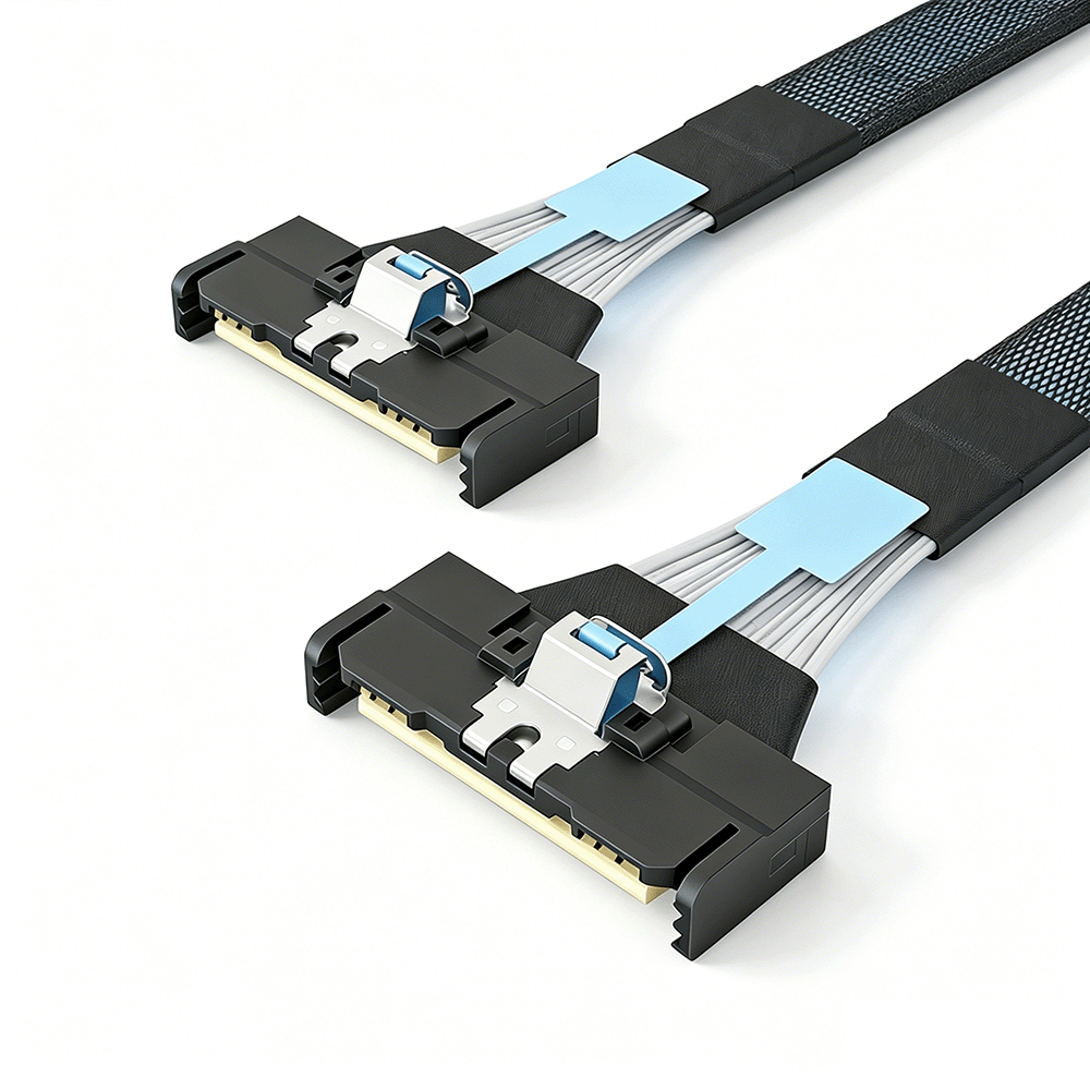
In 400G+ environments, the connector has evolved from a simple plug into the most critical bottleneck of your transmission chain. While many engineers obsess over the quality of the cabling, they often overlook the interface—the precise point where the signal either flows seamlessly or collides with impedance mismatches that destroy data integrity.
When signal frequencies reach these extreme levels, even the smallest physical gap at the contact point triggers severe return loss. Premium connectors are engineered for precision, not just durability.
The use of hard gold-plating processes is a strategic choice to neutralize microscopic surface irregularities, maintaining a stable, low-resistance path that keeps signal reflection at the absolute physical minimum. If an interface lacks the necessary mechanical tension, even the slightest vibration will cause pin-bounce, resulting in instantaneous data stream disruption that manifests as persistent link errors.
We must rethink the connector as a thermal management component. In high-density switch environments, the interface acts as a vital heat sink for the transceiver. Low-quality connectors often ignore thermal dissipation pathways, creating heat pockets that force hardware into thermal throttling. This creates a hidden performance degradation that is notoriously difficult to track within software logs, often leading engineers to blame the wrong components.
Consequently, you must bypass any interfaces that lack formal MSA compliance. The "cost savings" of using non-standard components are dwarfed by the permanent physical damage they cause to your switch port pins through poor mechanical tolerances. Treating the connector as a mission-critical component rather than a generic consumable is the hallmark of professional infrastructure design. In the microscopic world of high-speed signaling, a connection that is merely "good enough" is effectively a ticking time bomb for your network's long-term stability.
In high-speed networking, "set and forget" is a primary cause of systemic failure. Physical components—connectors, cables, and ports—degrade in ways software monitoring often ignores until a crash occurs. Moving from reactive fixes to proactive validation is essential for link stability.
Interfaces are not static; they oxidize, collect microscopic dust, and shift under thermal stress. At 400G+ speeds, even faint particulate matter disrupts the capacitive coupling required for reliable data transmission.
Maintenance Essential: Routine, structured cleaning cycles using high-grade solvents and lint-free tools are not optional—they are the baseline for maintaining the low-resistance connections your hardware demands.
Your maintenance regime must shift from checking link status to analyzing health trends. Monitoring Bit Error Rate (BER) serves as your early-warning system. A steady rise in corrected errors is a clear indicator of physical-layer fatigue, typically signaling shield degradation or connector wear. By treating these metrics as diagnostic signals rather than background noise, you isolate and replace failing hardware during scheduled windows instead of during emergency outages.
Network resilience is built on the discipline of verification. If you are not measuring insertion loss, verifying latch integrity, and tracking thermal behaviors, you are operating blindly.
Audit: Perform quarterly checks on link BER.
Inspect: Verify 360-degree connector seating annually.
Clean: Maintain a strict lint-free cleaning protocol for all high-speed interfaces.
Treat your physical layer as a precise instrument that requires constant calibration, not just a static set of wires. Proactive identification of physical strain is the only way to neutralize it before it forces a service-impacting event.
Signal loss can significantly affect the performance of high-speed networks, leading to increased latency, data errors, and reduced transmission efficiency. Understanding the most common causes helps network engineers and data center operators maintain stable and reliable connectivity.
As transmission distance increases, signal attenuation becomes more pronounced. Using cables beyond their recommended length can weaken signals and negatively impact network performance.
Nearby power equipment, wireless devices, and other electronic systems can introduce electromagnetic interference. Without proper shielding, high-speed cables may experience signal degradation and transmission errors.
Low-quality connectors, adapters, or cable assemblies can create insertion loss and impedance mismatches, reducing signal integrity across the network.
Sharp bends, excessive tension, or poor cable management can damage cable structures and affect signal transmission. Following recommended installation practices helps maintain optimal performance.
Extreme temperatures, humidity, and mechanical stress can gradually impact cable performance over time, increasing the risk of signal loss in demanding operating environments.
High-speed networking is an analog challenge where signal integrity is the only metric that matters. Reliability is not a coincidence; it is the deliberate result of precision routing, quality shielding, and proactive physical-layer maintenance. If you prioritize the integrity of your cables and interfaces, you eliminate the latent bottlenecks that cause systemic failure.
For critical infrastructure,


Copyright © 2025 Guangdong Jiumutong Communication Technology Co., Ltd All Rights Reserved
Designed by